Inductance of a Straight Conductor
From the knowledge of high school physics we know that a current carrying conductor produces a magnetic field around it. The magnetic flux lines are concentric circles with their direction specified by Maxwell's right hand thumb rule ( i.e., if the thumb of the right hand points towards the flow of current then the fingers of the fisted hand point towards the flux lines ). The sinusoidal variation in the current produces a sinusoidal variation in the flux. The relation between the inductance, flux linkage and the phasor current is then expressed as
where L is the inductance in Henry, λ is the flux linkage in Weber-turns and I is the phasor current in Ampere.
A. Internal Inductance
Consider a straight round (cylindrical) conductor, the cross-section of which is shown in Fig. 1.3. The conductor has a radius of r and carries a current I . Ampere's law states that the magnetomotive force (mmf) in ampere-turns around a closed path is equal to the net current in amperes enclosed by the path. We then get the following expression
 |
(1.4) |
where H is the magnetic field intensity in At/m, s is the distance along the path in meter and I is the current in ampere.
Let us denote the field intensity at a distance x from the center of the conductor by Hx. It is to be noted that Hxis constant at all points that are at a distance x from the center of the conductor. Therefore Hx is constant over the concentric circular path with a radius of x and is tangent to it. Denoting the current enclosed by Ix we can then write
 |
(1.5) |
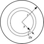
Fig. 1.3 Cross section of a round conductor.
If we now assume that the current density is uniform over the entire conductor, we can write
 |
(1.6) |
Substituting (1.6) in (1.5) we get
 |
(1.7) |
Assuming a relative permeability of 1, the flux density at a distance of x from the center of the conductor is given by
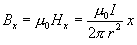 |
(1.8) |
where µ0 is the permeability of the free space and is given by 4π X 10-7 H/m.
The flux inside (or outside) the conductor is in the circumferential direction . The two directions that are perpendicular to the flux are radial and axial . Let us consider an elementary area that has a dimension of dx m along the radial direction and 1 m along the axial direction. Therefore the area perpendicular to the flux at all angular positions is dx X 1 m2 . Let the flux along the circular strip be denoted by dφ x and this is given by
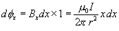 |
(1.9) |
Note that the entire conductor cross section does not enclose the above flux. The ratio of the cross sectional area inside the circle of radius x to the total cross section of the conductor can be thought about as fractional turn that links the flux dφ x. Therefore the flux linkage is
 |
(1.10) |
Integrating (1.10) over the range of x , i.e., from 0 to r , we get the internal flux linkage as
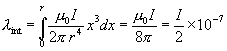 Wbt/m Wbt/m |
(1.11) |
Then from (1.3) we get the internal inductance per unit length as
 H/m H/m |
(1.12) |
For μ≠1, μr H/m
It is interesting to note that the internal inductance is independent of the conductor radius.
B. External Inductance
Let us consider an isolated straight conductor as shown in Fig. 1.4. The conductor carries a current I . Assume that the tubular element at a distance x from the center of the conductor has a field intensity Hx . Since the circle with a radius of x encloses the entire current, the mmf around the element is given by
 |
(1.13) |
and hence the flux density at a radius x becomes
 |
(1.14) |
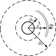
Fig 1.4 A Conductor with two external points
The entire current I is linked by the flux at any point outside the conductor. Since the distance x is greater than the radius of the conductor, the flux linkage dλx is equal to the flux dφx. Therefore for 1 m length of the conductor we get
 |
(1.15) |
The external flux linkage between any two points D1 and D2, external to the conductor is
 Wbt/m Wbt/m |
(1.16) |
From (1.3) we can then write the inductance between any two points outside the conductor as
 H/m H/m |
(1.17) |
For μ≠1, H/m where μr =relative permeability |
