Table 1. Tabular Calculations for Sewer Design
|
1 |
2 |
3 |
4 |
5 |
6 |
7 |
8 |
9 |
10 |
11 |
12 |
13 |
14 |
15 |
16 |
|
Manhole |
Length, m |
Average Sewage Flow, (2020) Litre/s |
Peak Flow, (2020) Litre/s |
Diameter, mm |
Slope |
Discharge, (2020) Litre/s |
Velocity, (2020) m/s |
Present Peak Flow, Year 2020 Litre/s |
Self-Clensing Velocity (2000) m/s |
Total Fall, m |
Invert Elevation, m |
||||
|
From |
To |
|
|
|
|
|
Full |
Actual |
Full |
Actual |
|
|
|
Upper |
Lower |
|
|
|
|
|
|
|
|
|
|
|
|
|
|
|
|
|
|
|
|
|
|
|
|
|
|
|
|
|
|
|
|
|
|
|
|
|
|
|
|
|
|
|
|
|
|
|
|
|
|
|
|
|
|
|
|
|
|
|
|
|
|
|
|
|
|
|
|
· A separate table is required for each trunk and main sewer
· Locate manholes on a particular sewer, giving each an identification number (columns 1-2)
· Determine the length of each section (between two manholes) (column 3)
· Determine the average sewage flow in each section, i.e., at the starting manhole in year 2020 (column 4)
· Determine the peak flow in each section by multiplying by the peaking factor (column 5)
· Determine the diameter and slope such that the sewer flows 0.8 full at ultimate peak flow (columns 6-7)
· Remember that a minimum diameter of 150 mm must be provided
· Calculate full discharge for the pipe diameter selected and compare with actual full discharge (col. 8-9)
· Calculate corresponding velocities and check that they are not less than 0.6m/s, or more than 3.0 m/s (columns 10-11)
· Calculate the present peak flow (Year 2000) in each sewer section (column 12)
· Calculate the velocity corresponding to present peak flow, and ensure that this is more than 0.6 m/s (column 13)
· Calculate total fall for each section (column 14)
· Calculate the invert level, i.e., level at the bottom of the sewer, at the upper end (starting manhole) and lower end (ending manhole) of the sewer section (columns 15-16)
H VII![]()
![]()
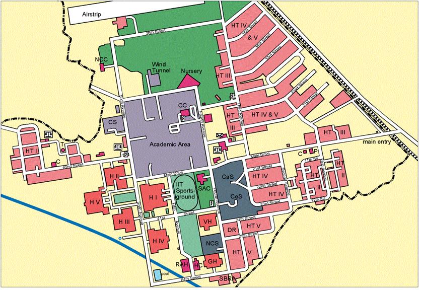
![]() Figure 1. Map of IIT
Figure 1. Map of IIT
Branch
Sewers
![]()


![]()
![]()
![]()

Figure 2. Proposed Sewers in IIT Kanpur
H VII


![]()