| |
Free Edge Effects:
Most of the composite laminate analysis uses the CLPT. CLPT assumes a planar state of stress along with the kinematic assumptions resulting from Kirchhoff assumptions. The determination of transverse stresses is not possible. Further, the CLPT is inadequate in determining the interlaminar stresses. The transverse stresses become significant in case of thick laminates under transverse loading. Further, these stresses are significant in case of geometric discontinuities like re-entrant corners, cut-outs, notches, ply-drops and material discontinuity as in the interfaces near the free edges. Thus, the state of stress in such regions is highly three dimensional and decays very fast inside the laminate. The CLPT fails to capture these stresses accurately in these regions. However, it is a good approximation away from these regions. It has been shown in the literature that the free-edge stress fields decays rapidly away from the laminate edges.
The free edge effects are due to discontinuous change of elastic material properties in the adjacent layers of the laminate. The development of interlaminar stresses near the free edges has been shown with the help of cross-ply symmetric laminate in the following paragraphs.
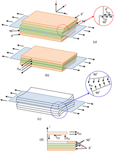
Consider a  laminate under axial extension as shown in Figure 9.3. The laminate under axial extension as shown in Figure 9.3. The  axis is along the length of the laminate, axis is along the length of the laminate,  axis is along the width and axis is along the width and  axis is along the thickness of the laminate. The coordinate is measured inward from the laminate edge. The CLPT predicts only intralaminar, that is, planar stresses whereas it neglects the interlaminar transverse normal axis is along the thickness of the laminate. The coordinate is measured inward from the laminate edge. The CLPT predicts only intralaminar, that is, planar stresses whereas it neglects the interlaminar transverse normal  and shear and shear  stresses. However, with the use of equilibrium equations one can determine these interlaminar stresses. It should be noted that the quality of these stresses depends upon the quality with which the planar stresses are determined. stresses. However, with the use of equilibrium equations one can determine these interlaminar stresses. It should be noted that the quality of these stresses depends upon the quality with which the planar stresses are determined.
The laminate shown has thickness of  and all the laminae are of equal thickness. Further, the laminate is sufficiently long. Therefore, the displacement components and all the laminae are of equal thickness. Further, the laminate is sufficiently long. Therefore, the displacement components  and and  are independent of coordinate. First consider that the laminae are not bonded to each other and are subjected to axial extension. Under these constraints, each layer is free to deform individually. From our earlier studies we know that, the transverse contraction of outer are independent of coordinate. First consider that the laminae are not bonded to each other and are subjected to axial extension. Under these constraints, each layer is free to deform individually. From our earlier studies we know that, the transverse contraction of outer  layers contract more than the inner layers contract more than the inner  layers. This is because the contraction in direction is perpendicular to the principal material directions of the layers’ material. Therefore, the displacement components will be discontinuous across the thickness. However, this is not true in practical situation as the layers are perfectly bonded leading to continuous displacement in the thickness direction. Hence, to maintain a continuous displacement one should apply tensile stresses layers. This is because the contraction in direction is perpendicular to the principal material directions of the layers’ material. Therefore, the displacement components will be discontinuous across the thickness. However, this is not true in practical situation as the layers are perfectly bonded leading to continuous displacement in the thickness direction. Hence, to maintain a continuous displacement one should apply tensile stresses  on layers whereas compressive stresses on layers. This fact is depicted in figure 9.3(b). These stresses are exactly predicted by the CLPT and together maintain the compatibility of the displacement. The absolute values of these stresses in and layers are identical and thus the resultant value through the thickness vanishes, that is, on layers whereas compressive stresses on layers. This fact is depicted in figure 9.3(b). These stresses are exactly predicted by the CLPT and together maintain the compatibility of the displacement. The absolute values of these stresses in and layers are identical and thus the resultant value through the thickness vanishes, that is,
 |
(9.1) |
Now it should be noted that the free edge is traction free. Therefore, the stresses should actually vanish. Thus, for equilibrium of forces in direction there must be interlaminar shear stresses  in the interface of the and layers (at in the interface of the and layers (at  ). This is depicted in the exploded view of Figure 9.3(a) ). This is depicted in the exploded view of Figure 9.3(a)
Thus, we can write
 |
(9.2) |
This holds true for high values of coordinate, that is, near the free edge. The variation of is shown in Figure 9.4(a).
It can be seen that these stress resultants do not share a common line of action, thus it leads to the bending moment about axis. Hence, for the equilibrium of this moment interlaminar stress  as depicted in Figure 9.3(c) arises at the interface between and layers (at ). Thus, we can write as depicted in Figure 9.3(c) arises at the interface between and layers (at ). Thus, we can write
 |
(9.3) |
The interlaminar stress acts only in - direction at the interface , the upper layer as shown in the free body diagram of Figure 9.3(d) must be sufficiently long and the resultant must vanish. Thus,
 |
(9.4) |
From this it is clear that the interlaminar stress must change its sign along - direction. The variation of is shown in Figure 9.4(b). The interlaminar stress shows a higher tensile value at the free edge.
Similarly one can show the development of other interlaminar shear stress  in angle ply laminates. For details, see [2,3]. in angle ply laminates. For details, see [2,3].
A thorough understanding of the free edge effect is essential for a designer so that there are minimum interlaminar stresses in the structure.
| Figure 9.3: The free edge effect in laminate under axial extension |
|