| |
Flexural Tests:
The flexural tests are conducted to determine the mechanical properties of resin and laminated fiber composite materials. Further, these tests are used to determine the interlaminar shear strength of a laminate, shear modulus, shear strength, tensile and compression moduli along with flexural and shear stiffness. These tests are not only used for composites but also for sandwich beams.
These tests are simple one. Further, they need simple instrumentation and equipment required. These tests conducted on beams of uniform cross section. These beam specimens do not require the end tabs.
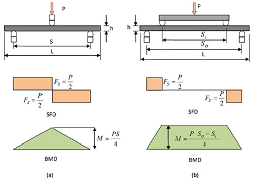
There are two methods to carry out these tests. The beam is a flat rectangular specimen and is simply supported close to its ends. In the first method the beam is centrally loaded. Thus gives three point bending. Since there are three important points (two end supports and one central loading point) along the span of the beam this method is called as three-point bending test. In the second method the beam is loaded by two loads placed symmetrically between the supports. In this method there are four important points (two end supports and two loading points) along the span of the beam. Thus, it gives four-point bending. Hence, this method is called four point bending. These methods are shown schematically in Figure 8.17(a) and (b), respectively. Also shown in this figure are the shear force diagram (SFD) and bending moment diagrams (BMD) related to the particular loading regimes.
From the shear force and bending moment diagrams it is clear that there is a stress concentration at the point of loading. However, for four point bending there is uniform bending moment and both shear force and interlaminar shear stress are zero between the loading points. Thus, it leads to the pure bending loading. Such a state of stress is desirable in testing.
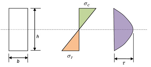
The properties are assumed to be uniform through the thickness as composite as it is a unidirectional composite or isotropic material. For such a material the normal stress varies linearly across the thickness. The maximum in compression is on one side and an equal maximum in tension on other side of the thickness and passes through zero at the mid-plane. The maximum normal stress is given as
 |
(8.32) |
where,  is the bending moment, is the bending moment,  is width and is width and  is the thickness of the specimen. Further, is the thickness of the specimen. Further,  and and  denote compressive and tensile normal stresses, respectively. denote compressive and tensile normal stresses, respectively.
The shear stress varies parabolic through the thickness with maximum at mid plane and zero at the outer surface. The maximum shear stress at the mid plane is given as
 |
(8.33) |
where  is the shear force on the specimen cross section. The normal stress and shear force variation through the thickness is shown in Figure 8.18. is the shear force on the specimen cross section. The normal stress and shear force variation through the thickness is shown in Figure 8.18.
The flexural response of the beam in three or four point bending test is obtained by recording the load applied and the resulting strain. The resulting strains are measured using the strain gages bonded on the beam in the gage length. It is clear from the distribution of the shear force and bending moment that the state of stress in specimens subjected to three and four-point bending tests are somewhat different. Thus, it may lead to differences in the results.
Figure 8.17: Shear force and bending moment diagrams for (a) three point and (b) four point bending test
|
Figure 8.18: Bending and shearing stresses in the thickness direction |
|