| |
B. Macro-level Failure Mechanism:
The macro-level mechanisms are laminate level mechanisms. Here, we are addressing the delamination. It is seen that the adjacent layers are bonded together by a thin layer of resin between them. This interface layer transfers the displacement and force from one layer to another layer. When this interface layer weakens or damages completely, it causes the adjacent layers to separate. This mode of failure is called delamination. It is shown in Figure 6.4.
Delamination reduces the strength and stiffness and thus limits the life of a structure. Further, it causes stress concentration in load bearing plies and a local instability leading to a further growth of delamination which results in a compressive failure of the laminate. In these two cases delamination leads to a redistribution of structural load paths which, in turn, precipitates structural failure. Hence, delamination indirectly affects the final failure of the structure thus affecting its life. Therefore, delamination is known as the most prevalent life limiting damage growth mode.
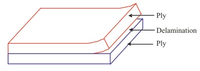 |
Figure 6.4: Macro-level damage mechanism (Delamination) |
Causes of Delamination:
Delamination can occur due to variety of reasons. The situations which can lead to delamination initiation and its growth are explained below.
a) Manufacturing Defects
This is the most common reason for existence of delaminations in a laminate. Improper laying of laminae, insufficient curing temperature; pressure and duration of curing, air pockets and inclusions are some of the reasons which lead the manufacturing defects causing delamination.
b) Loading Generating Transverse Stresses
The interface is weaker in transverse strength as compared to the layers. Hence, its failure is dominated by the transverse stresses. The interface generally fails under tensile load applied normal to it (see Figure 6.5(a)). Also, the delamination can take place due to compressive stresses in its inplane direction causing buckling, which in turn, causes delamination.
The inplane loads applied to angle ply laminate can cause delamination in it. This is because the bending-stretching coupling can give rise to transverse stresses in the interface. A schematic illustration of how axial tensile loading of angle ply laminates cause rotation of the plies is shown in Figure 6.5(b). This rotation of the plies generates the interlaminar shear stresses, which is one of the crucial factors in delamination.
Note: The Inter-laminar stresses are the stresses in the interface between two adjacent layers. The existence to these stresses is shown in various references. Further, these stresses can be very high locally depending upon various situations. We will also see the existence of these stresses in a later chapter.
c) Laminate Geometry
The geometry of the laminate can lead to a three dimensional state of stress locally in the interface leading to high interlaminar stresses. Some of the geometries of the laminate and structures are shown below in which delamination damage will be a major damage mode.
- Free Edge:
The free edges of the laminate have very high transverse normal  and shear and shear  stresses. It is shown that significant interlaminar stresses are induced in regions near the laminate free edges. Interlaminar stresses near the free edges can be controlled to an extent through the choice of materials, fibre orientations, stacking sequence, layer thickness and the use of functionally graded materials. However, when free edges are present, interlaminar stresses can be completely eliminated through the use of a homogeneous material, locally. stresses. It is shown that significant interlaminar stresses are induced in regions near the laminate free edges. Interlaminar stresses near the free edges can be controlled to an extent through the choice of materials, fibre orientations, stacking sequence, layer thickness and the use of functionally graded materials. However, when free edges are present, interlaminar stresses can be completely eliminated through the use of a homogeneous material, locally.
The delamination shown in Figure 6.4, infact, is an edge delamination.
- Notch:
Notch in the laminates acts like an external crack giving rise to high three dimensional stress state in the vicinity of the notch (See Figure 6.5(c)).
- Cut-out:
Cutouts are inevitable in structures. Cutouts are made to pass electric wires; fluid passage as in the wings, doors and windows in the fuselage of an air vehicle. These are, especially in aerospace vehicles, made also to reduce the weight of the component. The cutout boundaries act like free edges leading to significant transverse stresses. This is one of the most common site for onset of delamination. A laminate with cutout is shown in Figure 6.5(d).
- Ply Drop/Termination:
The optimum design of composite structures in air vehicles is important. As a result of the optimization (e.g. weight minimization) process or sometimes purely due to geometric requirements/constraints, one or more of the plies have to be terminated (also known as “ply drop”) inside the laminate. The region of ply termination acts like a region of high stresses for neighbouring laminae which can be a reason for delamination of the plies adjacent to the ply drop region. A ply drop in laminate is shown in Figure 6.5(e).
- Bonded Joints:
Sometimes laminates are bonded together using resin. Improper bonding leads to weaker joints. When such weak joints are subjected to serve loading conditions delamination can occur. A bonded joint in composite is shown in Figure 6.5(f).
- Bolted Joints:
Sometimes it is required to attach the composite structures to metallic structures. In such situations, bolted joints are imperative. The free edges of the cutout made in composite and additional load applied by tightening of the joint leads to a complex local state of stress. When these composite structures are T or L sections carrying additional loads, the situation is the worst. In such a situation delamination starts at cutout edges or at the curved edges of the T or L sections. A L-bolted joint is shown in Figure 6.5(g).
- Doublers:
These are needed due to geometric or functional requirements in the structures. In this case a laminate is split into two or more set of laminae (or vice a versa). Thus, at the bifurcation laminae (or where the laminae join together to form laminate) give rise to high stresses. These locations are potential zones for delamination initiation. Typical doublers are shown in Figure 6.5(h).
Suppression of Delamination:
Several possible design changes are suggested for delaying/suppressing the onset and growth of delamination.
The primary cause of delamination is the low interlaminar fracture toughness. This is due to brittle nature of most resins (epoxy) used as matrix material, which have low mode I fracture toughness. The suggested models for improving this property are:
Adding thermoplastics, interleafing soft and hard layers, increasing length of cross-links Adding second phase materials to matrix like rubber; chopped fibre, fibrils, etc. Through thickness reinforcement by 3D braiding or stitching
|